Impact of Timing Effects on Safety Mechanisms

Introduction
Today’s automobiles are safer thanks in part to the advanced driver-assistance systems (ADAS) that watch over the driver and its passengers. However, the ECUs upon which these system are based are incredibly complex, incorporating thousands of software components. While each software component is tested for safe operation in isolation, functional issues often show when they are integrated together.
During development, automotive engineering teams determine various Safety Goals (SG). The time between the occurrence of a fault and the SG being violated is termed the Fault Tolerant Time Interval (FTTI). ISO 26262 requires that FTTIs be identified and appropriately partitioned.
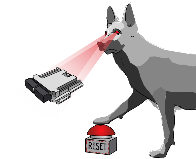
In order to guarantee that the ECU remains operationally safe under all conditions, a watchdog is used. Such devices, typically external to the processor, are also considered a necessity above certain ASIL level. If the watchdog is not serviced on time, an indication of a fault within the ECU, it resets the processor. This helps to ensure the safety of the solution but obviously impacts its availability.
The problem is, in some cases the watchdog is triggered although there is no fault with the ECU. This can happen because, due to jitter in executing critical code sections, resulting in a failure to adhere to FTTIs. Worst case, such false triggering can result in the OEM issuing contractual penalties.
Causes of failure to adhere to FTTIs
The processor assigned to making a safety-relevant decision receives data from a wide range of sources at varying rates. Some sensors may be connected directly. Time variations in processing such data are a local challenge, depending on available processing performance, task priorities, and the number of interrupts occurring at any one time. Other sensor data comes from separate ECUs. These ECUs’ processing load additionally impacts the rate with which this data can be processed, as does the capacity of the bus (e.g., CAN, CAN-FD) selected to deliver the data.
Understanding filtering and debouncing of errors
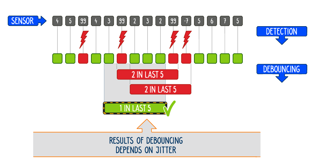
Not all the data provided will necessarily be used by the functionally-safe components in the system. Some samples may get discarded to weed out those that are out of range or change too quickly using approaches such as sliding windows or under-sampling. Such debouncing algorithms keep tabs on the number of input data issues, registering errors if n erroneous values occur in a sample window of size q.
However, the triggering of these debouncing algorithms and the control loops that use the data are also subject to jitter. Thus, although the number of erroneous samples may be high, it may well be that no issue is reported due to jitter in the debounce algorithm. And the reverse may also be true, with a low number of erroneous samples resulting in the registration of an issue simply due to the phase of code execution at that moment in time.
By understanding the impact of timing on these algorithms, it is possible to generate suitable test vectors to ensure conformance with the FTTIs.
Finding timing issues before they occur in hardware
Due to their immense complexity and the quantity of sensor data, steering, chassis control, and electric drivetrain systems often suffer such issues when testing FTTIs. Not only is the definition of tests challenging, their execution on the system’s hardware is also incredibly difficult to implement. Such dynamic architectures benefit greatly from simulation early on in the development process, coupled with tests that accompany the design through each stage of the development process.
Thankfully this is made possible with chronSUITE, a suite of tools from INCHRON that enable the creation of tests for complex corner case temporal situations. chronSIM allows such applications to be tested as model-based simulations, accommodating the timing impact of the hardware and software of multiple ECUs and in-vehicle networks. Furthermore, the model can take into account the impact of time synchronization and drifting clocks. The results of simulations are analyzed in chronVIEW, the same tool used to review hardware traces from an ECU’s processor. Especially challenging timing issues may be tackled with chronVAL, which uses sensitivity analysis to detect such timing bottlenecks and highlights sporadic violations using formal verification methods.
If you or your team are having issues testing FTTIs, get in touch with the INCHRON team using the form below – we’d be more than happy to help!
Any questions?
Feel free to contact us.

