Event-Chain-Centric Architecture Design of Driver Assistance Systems

Developing Part of an Automotive System
Developers of automotive electronics rarely deliver an end-to-end system. Instead, they are typically responsible for part of the system while the OEM sources the remaining elements from other suppliers. Thus, for Advanced Driver Assistance System (ADAS) solutions such as emergency brake assist (EBA), the central electronic control unit (ECU) must be developed without control over the design of the sensors or actuators. This means that the chosen supplier must allow for aspects of the solution they are not responsible for.
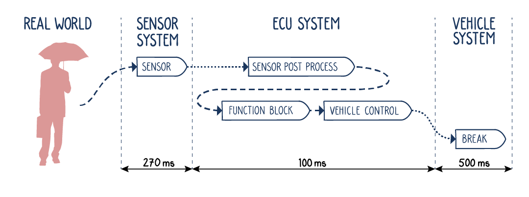
System architects develop models at the logical architecture level to ensure that the entire system’s behavior is understood and considered during development. These models allow the development team to build a picture of the end-to-end behavior of the entire system, defining the various paths from sensor to actuator in the form of event chains. This allows the end-to-end data flow to be understood and abstracted from the technical details, such as sensor type, vehicle bus used, and the processor in the ECU. This focus on event chains allows a dynamic architecture design to be constructed that is event-chain-centric.
Determination of Event Chain Timing
The timing for an end-to-end event chain is derived from a safety standard, such as Euro NCAP. For example, in an EBA system, the time available for the sensor-to-actuator path is the total time derived from the standard minus the time required for vehicle deceleration. This result is then broken down further into the timing for the sensor to deliver data, the ECU to process the data and trigger the actuator, and the actuator to respond. Finally, the time available for the ECU can be broken down further, defining how much time is available for each processing stage within the ECU. For an EBA, this will include sensor post-processing, arbitration, rating, planning, and vehicle control steps.
With the timings defined, a model of the system is constructed using a UML (Unified Modeling Language) development tool. From here, the model is exported to a simulation tool to validate the timing requirements. To ensure all variations in timing are reflected, the response time for each stage can be defined. The regularity of trigger signals, as well as their jitter, will also be included.
System Simulation and Verification
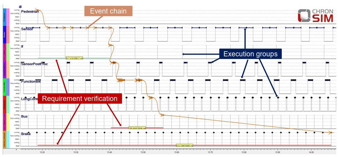
With a model defined, the dynamic system behavior is simulated. This is undertaken with a tool such as INCHRON’s chronSIM, part of the chronSUITE timing toolkit. With each simulation pass, the entire event chain time is calculated. Every result is compared against the real-time timing requirements defined by the system architects. chronSIM can be configured to automatically compare the results with the timing requirement, allowing the development team to establish areas of concern in the design quickly.
Evaluating Results and Optimizing the Design
Timing results are provided as a histogram. Variation in event chain latency is linked to the jitter of the individual timer elements. The development team will need to determine if the end-to-end timing requirement has been broken and, if so, what changes to the architecture must be made to rectify the issue. Significant variations or failures to meeting the timing requirements will need to be addressed at the logical architecture level. Here, the degrees of freedom can include activation types (data or event driven), communication delays, and activation periods, to name but a few. Even if end-to-end timing has been fulfilled, wide variation in event chain latency may be considered unacceptable. Here the team can also use the simulation results to find architectural improvements that limit wide variations in end-to-end timing.
The Move to Integration Testing
With the model configured to meet the timing requirements, the design can move to the implementation, then the integration stage. The challenge with timing-related failures is that they manifest themselves as functional failures. Additionally, these functional failures occur sporadically and only under very specific test conditions. For minimal overhead, the application software can be configured to generate trace information from which the timing within the ECU can be recovered. Such data requires very little bandwidth and is easily accommodated on an existing vehicle bus. The data collected can be imported back into chronSUITE’s timing visualization and analysis tool chronVIEW, allowing the actual system timing to be compared with the original model. Approaches to mitigate any issues found can be tested by simulating the updated model before being deployed to the hardware again for integration testing.
Only with consideration of end-to-end timing is it possible to develop the robust architectures required by today’s modern safety-critical ADAS technology. The event-chain-centered architecture design discussed here has proven itself in practice to make the design of complex systems manageable, resolve intermittent functional failures rapidly, and shorten the development time of automotive systems.
If you’d like to learn more about how Valeo used this approach to develop an emergency brake assist product, download our ESE Congress paper “Event-chain-centric architecture design of Driver Assistance Systems.”
If you’re intrigued by the event-chain-centric development approach discussed here and would like to learn more, use our contact form to get in touch to arrange a free consultation:


